Build package
Build Berkeley Humanoid Lite
UC Berkeley Hybrid Robotics Lab · Humanoid · research · 2025
Open-source sub-$5,000 humanoid built from desktop-3D-printed cycloidal gearboxes and off-the-shelf parts; 0.8 m, 16 kg, 22 DOF.
Two ways to get Berkeley Humanoid Lite
Compare all →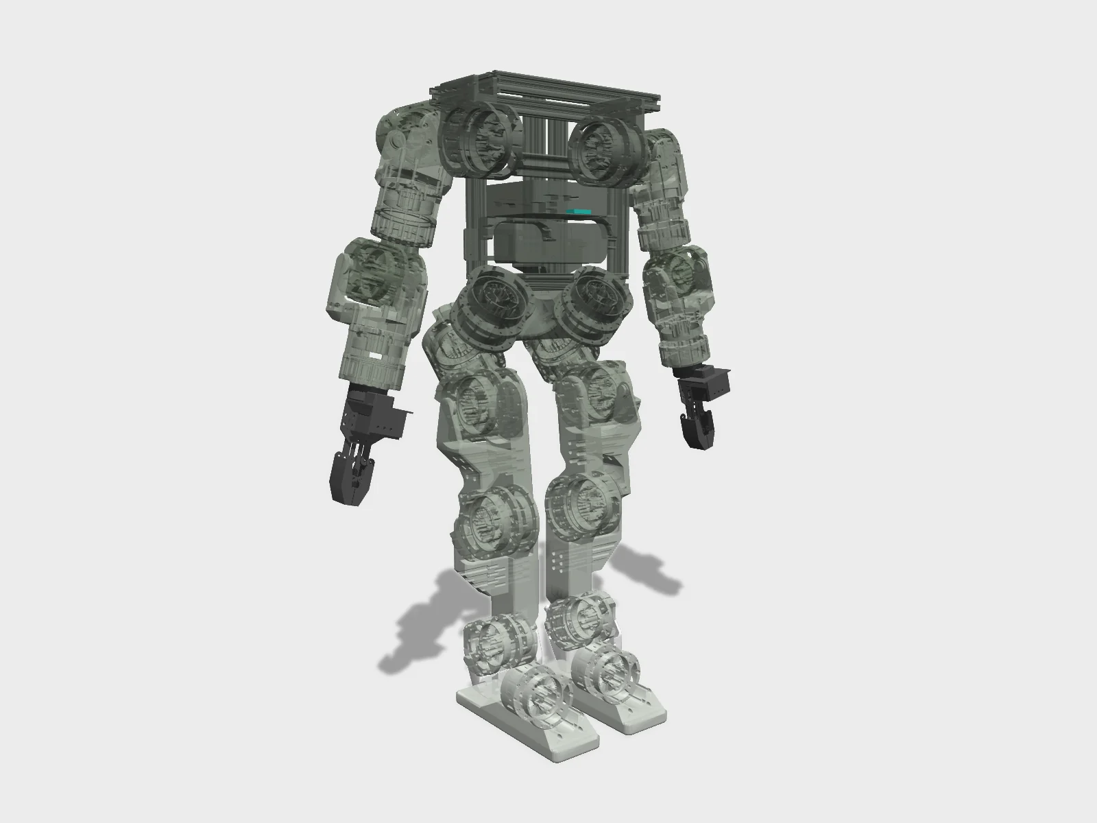
- Drawing
- /berkeley/humanoid-lite
- Maker
- UC Berkeley Hybrid Robotics Lab
- Country
- Berkeley, US
- Package rev
- v0.1.0
- Level
- L2 Sim-verified
- Availability
- DIY
- Openness
- 100/100
- HW licence
- CC-BY-SA-4.0
- Last checked
- 2026-09-24
- Height
- 80 cm
- Mass
- 16 kg
- DOF
- 22
- Actuators
- BLDC motors with 3D-printed cycloidal gearboxes
6 DOF per leg, 5 DOF per arm. Paper arXiv:2504.17249. L2 on the same basis as other maker-published MJCF + policy packages: MJCF in berkeley-humanoid-lite-assets, ONNX policies in the main repo's checkpoints/.
Configure
Saved in the URL. Share the link to share the build.Source
One cart across 3 vendors · prices in USD as listed37 lines · 1,421 parts · 3 without an offer in US · 34/37 lines sourced in 2+ regions (L3 gate)
| # | Part | Category | Qty | Unit | Line | Offer |
|---|---|---|---|---|---|---|
Amazon32 lines · $3,496.86 | ||||||
| 1 | MAD Components M6C12 150KV BLDC motor (6512 actuator) motor.mad-m6c12-150kv | actuator | 10 | $129.00 | $1,290.00 | Amazon |
| 2 | MAD Components 5010 110KV BLDC motor (5010 actuator) motor.mad-5010-110kv | actuator | 12 | $84.00 | $1,008.00 | Amazon |
| 3 | AS5600 I2C magnetic position encoder (with diametric magnet; resistor-modified) encoder.as5600 · MPN AS5600 | sensor | 22 | $3.30 | $72.60 | Amazon |
| 4 | MR106-2RS bearing (input shaft / cycloidal disk / output shaft) bearing.mr106-2rs · MPN MR106-2RS | structure | 286 | $0.87 | $248.82 | Amazon |
| 5 | 6701-2RS bearing (cycloidal disk to output shaft) bearing.6701-2rs · MPN 6701-2RS | structure | 44 | $0.94 | $41.36 | Amazon |
| 6 | 6811ZZ bearing (6512 output shaft to housing) bearing.6811zz · MPN 6811ZZ | structure | 20 | $5.00 | $100.00 | Amazon |
| 7 | 6809ZZ bearing (5010 output shaft to housing) bearing.6809zz · MPN 6809ZZ | structure | 24 | $2.26 | $54.24 | Amazon |
| 8 | 6803-2RS bearing (leg pitch-actuator linkage) bearing.6803-2rs · MPN 6803-2RS | structure | 6 | $2.87 | $17.22 | Amazon |
| 9 | M3 x 55 mm screw (mounting actuator housing) fastener.m3x55 | fastener | 128 | $0.26 | $33.28 | Amazon |
| 10 | M3 x 30 mm screw (6512 output shaft) fastener.m3x30 | fastener | 60 | $0.19 | $11.40 | Amazon |
| 11 | M3 x 25 mm screw (5010 output shaft) fastener.m3x25 | fastener | 72 | $0.19 | $13.68 | Amazon |
| 12 | M2 x 3 x 3.5 mm heat-set threaded insert (encoder mount) fastener.insert-m2x3x3.5 | fastener | 88 | $0.07 | $6.16 | Amazon |
| 13 | M3 x 4 x 5 mm heat-set threaded insert fastener.insert-m3x4x5 | fastener | 528 | $0.08 | $42.24 | Amazon |
| 14 | M4 x 15 mm hex standoff (6512 input shaft stiffener) fastener.standoff-m4x15 | fastener | 10 | $0.69 | $6.90 | Amazon |
| 15 | M4 x 12 mm hex standoff (5010 input shaft stiffener) fastener.standoff-m4x12 | fastener | 12 | $0.40 | $4.80 | Amazon |
| 16 | Mini PC (Intel N95; docs reference Beelink N95 NUC) compute.mini-pc-n95 | compute | 1 | $129.00 | $129.00 | Amazon |
| 17 | 6S LiPo battery (paper: 6S 4000 mAh) power.lipo-6s | power | 1 | $70.20 | $70.20 | Amazon |
| 18 | USB-CAN adapter (one per limb bus can0..can3) electronics.usb-can | electronics | 4 | $16.99 | $67.96 | Amazon |
| 19 | USB hub electronics.usb-hub | electronics | 2 | $17.99 | $35.98 | Amazon |
| 20 | BNO085 IMU sensor (original build, via Arduino Nano) sensor.imu-bno085 · MPN BNO085 | sensor | 1 | $12.76 | $12.76 | Amazon |
| 21 | Aluminum extrusion 250 mm structure.extrusion-250mm | structure | 2 | $4.25 | $8.50 | Amazon |
| 22 | Aluminum extrusion 200 mm structure.extrusion-200mm | structure | 4 | $3.75 | $15.00 | Amazon |
| 23 | Aluminum extrusion 150 mm structure.extrusion-150mm | structure | 2 | $3.00 | $6.00 | Amazon |
| 24 | Aluminum extrusion 100 mm structure.extrusion-100mm | structure | 3 | $3.25 | $9.75 | Amazon |
| 25 | Aluminum extrusion inner bracket structure.inner-bracket | structure | 24 | $0.65 | $15.60 | Amazon |
| 26 | 24V to 12V regulator power.reg-24-12 | power | 1 | $16.99 | $16.99 | Amazon |
| 27 | 12V to 5V regulator power.reg-12-5 | power | 1 | $4.49 | $4.49 | Amazon |
| 28 | Voltage monitor power.voltage-monitor | power | 1 | $14.99 | $14.99 | Amazon |
| 29 | Current monitor power.current-monitor | power | 1 | $20.98 | $20.98 | Amazon |
| 30 | Circuit breaker power.circuit-breaker | power | 1 | $19.99 | $19.99 | Amazon |
| 31 | Servo motor claw gripper (LewanSoul/Hiwonder BigClaw) other.gripper-claw | other | 2 | $35.99 | $71.98 | Amazon |
| 32 | PLA filament (Hatchbox or Bambu Lab PLA Basic) printed.pla-filament | printed | 1 | $25.99 | $25.99 | Amazon |
DigiKey1 line · $417.34 | ||||||
| 33 | STMicroelectronics B-G431B-ESC1 motor controller esc.b-g431b-esc1 · MPN B-G431B-ESC1 | electronics | 22 | $18.97 | $417.34 | DigiKey |
Hiwonder1 line · $89.99 | ||||||
| 34 | Hiwonder IM10A USB IMU (recommended alternative, not in sheet total) sensor.imu-im10a | sensor | 1 | $89.99 | $89.99 | Hiwonder |
No offer in this region3 lines · $200.00 | ||||||
| 35 | Actuator cables & connectors (misc, per actuator) cable.actuator-misc | cable | 22 | $5.00list price | $110.00 | No offer found yet |
| 36 | Misc fasteners (robot-level lot) fastener.misc-lot | fastener | 1 | $40.00list price | $40.00 | No offer found yet |
| 37 | Misc cables & connectors (robot-level lot) cable.misc-lot | cable | 1 | $50.00list price | $50.00 | No offer found yet |
| Cart total · US | 1,421 | $4,204.19 | All lines priced | |||
Fabricate
Planned for a 256 mm bed- Fabricated parts
- 30
- Print time (sum)
- —
- Material (sum)
- 2,400 g
- Plates · estimate
- ≈ 12
Plates is an estimate, not a slice: the package has no part footprints, so it assumes about 200 g of FDM parts per plate on a 256 mm bed, scaled by bed area (256 mm ≈ 200 g/plate). Parts larger than your bed are not detected.
| Part | Process | Material | Qty | h / part | g / part | Profile |
|---|---|---|---|---|---|---|
6512 cycloidal actuator: housing, output shaft, motor shell (Actuator Housing Profile) + cycloidal disk, input shaft, motor shaft, spacers (Actuator Shaft Profile) printed.actuator-6512-housing-set | FDM | PLA | 10 | — | 120 | source |
5010 cycloidal actuator: housing, output shaft, motor shell (Actuator Housing Profile) + cycloidal disk, input shaft, motor shaft, spacers (Actuator Shaft Profile) printed.actuator-5010-housing-set | FDM | PLA | 12 | — | 100 | source |
Upper-body structural parts plate (print twice, mirrored along X, for left/right arms) printed.upper-body-plate | FDM | PLA | 2 | — | — | source |
Lower-body structural parts plate (print twice, mirrored along X, for left/right legs) printed.lower-body-plate | FDM | PLA | 2 | — | — | source |
USB-CAN adapter case printed.usb-can-case | FDM | PLA | 4 | — | — | source |
Assemble
Every step ends in a check- Steps
- 14
- Subassemblies
- 7
- Hands-on time (sum)
- —
- Critical path
- —
- Your progress · this device
- —
14 steps have no time estimate; times above are lower bounds.
Steps, in build order
- fabrication01
Print actuator and structural parts
Download the MakerWorld .3mf projects from the Releases page. Print housings/output shafts/motor shells with the Actuator Housing Profile and cycloidal disks/input shafts/motor shafts/spacers with the Actuator Shaft Profile; structural body plates can use faster settings and are printed twice, mirrored along X.
CHECKParts for 10x 6512 and 12x 5010 actuator sets plus mirrored upper- and lower-body plates are printed with no warping on bearing seats.- Parts in
- PLA filament (Hatchbox or Bambu Lab PLA Basic)printed.pla-filament
- Tools
- FDM printer >=200x200x200 mm (Bambu X1C or Ender-3 V3 SE tested)
- Torque
- —
- Time
- —
- After
- Start
- actuator02
Modify the AS5600 encoder boards
Swap the resistors on each AS5600 board per the linked tutorial to change its configuration. Then solder VCC, GND, SDA and SCL wires onto the corresponding pads (yellow = SDA, green = SCL, 30 AWG).
CHECKAll 22 AS5600 boards have the resistor modification done and four wires soldered to VCC/GND/SDA/SCL.- Parts in
- AS5600 I2C magnetic position encoder (with diametric magnet; resistor-modified)encoder.as5600
- Tools
- soldering iron, flux
- Torque
- —
- Time
- —
- After
- Start
- 03
Glue encoder magnet to motor shaft
Hot-glue the diametrically magnetised magnet supplied with the AS5600 to the end of each motor rotor shaft. Ordinary axially magnetised round magnets will not work with the encoder.
CHECKEach of the 22 motors has the encoder's own magnet centred and firmly glued on the shaft end.- Parts in
- MAD Components M6C12 150KV BLDC motor (6512 actuator)motor.mad-m6c12-150kv
- MAD Components 5010 110KV BLDC motor (5010 actuator)motor.mad-5010-110kv
- AS5600 I2C magnetic position encoder (with diametric magnet; resistor-modified)encoder.as5600
- Tools
- hot glue gun
- Torque
- —
- Time
- —
- After
- Start
- 04
Assemble the cycloidal actuators
Install M2 and M3 heat-set inserts, then follow the actuator assembly video: bearings into the cycloidal disk, input and output shafts, then close the housing with M3 x 55 screws. The 6512 uses 6811ZZ output bearings and M3 x 30 output screws; the 5010 uses 6809ZZ and M3 x 25.
CHECKThe output shaft turns smoothly by hand with no binding through a full revolution and the encoder sits over the motor magnet.- Parts in
- 6512 cycloidal actuator: housing, output shaft, motor shell (Actuator Housing Profile) + cycloidal disk, input shaft, motor shaft, spacers (Actuator Shaft Profile)printed.actuator-6512-housing-set
- 5010 cycloidal actuator: housing, output shaft, motor shell (Actuator Housing Profile) + cycloidal disk, input shaft, motor shaft, spacers (Actuator Shaft Profile)printed.actuator-5010-housing-set
- MR106-2RS bearing (input shaft / cycloidal disk / output shaft)bearing.mr106-2rs
- 6701-2RS bearing (cycloidal disk to output shaft)bearing.6701-2rs
- 6811ZZ bearing (6512 output shaft to housing)bearing.6811zz
- 6809ZZ bearing (5010 output shaft to housing)bearing.6809zz
- M3 x 4 x 5 mm heat-set threaded insertfastener.insert-m3x4x5
- M2 x 3 x 3.5 mm heat-set threaded insert (encoder mount)fastener.insert-m2x3x3.5
- M3 x 55 mm screw (mounting actuator housing)fastener.m3x55
- M3 x 30 mm screw (6512 output shaft)fastener.m3x30
- M3 x 25 mm screw (5010 output shaft)fastener.m3x25
- M4 x 15 mm hex standoff (6512 input shaft stiffener)fastener.standoff-m4x15
- M4 x 12 mm hex standoff (5010 input shaft stiffener)fastener.standoff-m4x12
- Tools
- soldering iron with heat-insert tip, heat insert stand, hex keys M2-M6
- Torque
- —
- Time
- —
- 05
Solder motor, encoder and CAN to the ESC
Safety · human-verified requiredConnect encoder, motor phases and CAN to the B-G431B-ESC1 following the wiring diagram, using 14 AWG silicone wire for power (red/white +, black GND) and 30 AWG for CAN (yellow CAN-H, green CAN-L). The ESC's CAN solder pads are very fragile, so use plenty of flux and never put strain on the pads.
CHECKContinuity test passes for each CAN-H/CAN-L and I2C line, and there is no short between the power + and GND pads.This step can hurt a person or ruin parts. Its instructions need sign-off by a human who has done it before relying on them. Stop and ask if anything differs from what you see.
- Parts in
- STMicroelectronics B-G431B-ESC1 motor controlleresc.b-g431b-esc1
- Actuator cables & connectors (misc, per actuator)cable.actuator-misc
- Tools
- soldering iron, flux
- Torque
- —
- Time
- —
- firmware06
First-time flash of motor controller firmware
Clone Recoil-Motor-Controller-BESC, set FIRST_TIME_BOOTUP to 1 in Core/Inc/motor_controller_conf.h, and Run over Micro-USB (accept the ST-LINK firmware update on new boards). Power-cycle the board, then set the flag back to 0.
CHECKSTM32CubeIDE reports a successful download and the board re-enumerates after the power cycle.- Parts in
- STMicroelectronics B-G431B-ESC1 motor controlleresc.b-g431b-esc1
- Tools
- STM32CubeIDE, Micro-USB cable
- Torque
- —
- Time
- —
- After
- 05
- 07
Set CAN ID and motor profile
Set DEVICE_CAN_ID from the Joint ID Mapping, uncomment the matching MOTORPROFILE (MAD_M6C12_150KV or MAD_5010_110KV), and set LOAD_ID_FROM_FLASH and LOAD_CONFIG_FROM_FLASH to 0. Run, power-cycle, then set the flags back to 1 and Run a final time (four Runs in total).
CHECKAfter power-cycling, the ESC LED blinks at about 1 Hz.- Parts in
- STMicroelectronics B-G431B-ESC1 motor controlleresc.b-g431b-esc1
- Tools
- STM32CubeIDE
- Torque
- —
- Time
- —
- After
- 06
- 08
Ping and calibrate electrical offset
Safety · human-verified requiredBring up SocketCAN with `sudo ip link set can0 up type can bitrate 1000000`, then run motor/ping.py. With the actuator unloaded and free to spin, run calibrate_electrical_offset.py; it draws about 1 A, turns one revolution CCW and then one CW.
CHECKping.py prints 'Motor is online', and calibration rotates CCW first. If it rotates CW first, swap two phase wires or set MOTOR_PHASE_ORDER to -1.This step can hurt a person or ruin parts. Its instructions need sign-off by a human who has done it before relying on them. Stop and ask if anything differs from what you see.
- Parts in
- USB-CAN adapter (one per limb bus can0..can3)electronics.usb-can
- Tools
- USB-CAN adapter, bench power supply
- Torque
- —
- Time
- —
- After
- 07
- 09
Bench-test actuator motion
Safety · human-verified requiredRun move_actuator.py to command a sinusoidal position trajectory. Start with small kP, kD and torque limit, and press Ctrl+C to stop if anything unexpected happens.
CHECKThe actuator follows the sinusoid smoothly without buzzing, overheating, or losing CAN connection.This step can hurt a person or ruin parts. Its instructions need sign-off by a human who has done it before relying on them. Stop and ask if anything differs from what you see.
- Parts in
- —
- Tools
- —
- Torque
- —
- Time
- —
- After
- 08
- assembly10
Build arms and legs
Follow the arm and leg assembly videos to integrate 5 actuators into each arm and 6 into each leg. The leg pitch linkage uses 6803-2RS bearings, and a servo claw gripper mounts on each arm.
CHECKEach limb moves through its Joint ID Mapping range (e.g. knee 0-140 deg) by hand without collision.- Parts in
- Upper-body structural parts plate (print twice, mirrored along X, for left/right arms)printed.upper-body-plate
- Lower-body structural parts plate (print twice, mirrored along X, for left/right legs)printed.lower-body-plate
- 6803-2RS bearing (leg pitch-actuator linkage)bearing.6803-2rs
- Servo motor claw gripper (LewanSoul/Hiwonder BigClaw)other.gripper-claw
- Misc fasteners (robot-level lot)fastener.misc-lot
- Tools
- hex keys M2-M6
- Torque
- —
- Time
- —
- After
- 09
- 11
Assemble torso frame and full robot
Build the aluminum-extrusion base with inner brackets and mount the mini PC, USB hubs and electronics. Then attach the arms and legs following the 'Entire robot' video.
CHECKAll four limbs are rigidly attached and the robot stands on its own on a stand without any frame flex.- Parts in
- Aluminum extrusion 250 mmstructure.extrusion-250mm
- Aluminum extrusion 200 mmstructure.extrusion-200mm
- Aluminum extrusion 150 mmstructure.extrusion-150mm
- Aluminum extrusion 100 mmstructure.extrusion-100mm
- Aluminum extrusion inner bracketstructure.inner-bracket
- Mini PC (Intel N95; docs reference Beelink N95 NUC)compute.mini-pc-n95
- USB hubelectronics.usb-hub
- Tools
- —
- Torque
- —
- Time
- —
- After
- 10
- electrical12
Wire power bus, CAN buses and IMU
Safety · human-verified requiredFollow the wiring diagram: an XT60 main power bus with each actuator branched off on XT30 (WAGO connectors are fine for debugging). Solder signal cables and cover the joints with heat shrink. Each limb's CAN goes to its own USB-CAN adapter terminal in the order CAN-L, CAN-H, GND, and the IM10A USB IMU is recommended over the BNO085+Arduino Nano setup.
CHECKWith the breaker open, there is no short between bus + and GND. After closing it, the voltage monitor reads the battery voltage and four CAN interfaces enumerate on the PC.This step can hurt a person or ruin parts. Its instructions need sign-off by a human who has done it before relying on them. Stop and ask if anything differs from what you see.
- Parts in
- 6S LiPo battery (paper: 6S 4000 mAh)power.lipo-6s
- Circuit breakerpower.circuit-breaker
- 24V to 12V regulatorpower.reg-24-12
- 12V to 5V regulatorpower.reg-12-5
- Voltage monitorpower.voltage-monitor
- Current monitorpower.current-monitor
- USB-CAN adapter (one per limb bus can0..can3)electronics.usb-can
- Hiwonder IM10A USB IMU (recommended alternative, not in sheet total)sensor.imu-im10a
- Misc cables & connectors (robot-level lot)cable.misc-lot
- Tools
- —
- Torque
- —
- Time
- —
- After
- 11
- software13
Set up on-board computer and verify buses
Install Ubuntu 22.04 and the build-essential, cmake, net-tools, can-utils and python3-pip packages, then start the CAN transports with scripts/start_can_transports.sh. Ping each joint, or run the all-joints check, then test the IMU and the UDP joystick bridge.
CHECKAll 22 joints respond across can0-can3 (CAN IDs 1-14 per the mapping), and test_imu prints live orientation.- Parts in
- Mini PC (Intel N95; docs reference Beelink N95 NUC)compute.mini-pc-n95
- Tools
- —
- Torque
- —
- Time
- —
- After
- 12
- bring-up14
Calibrate joints and run locomotion policy
Safety · human-verified requiredAfter each power cycle, run calibrate_joints.py and move every joint to its mechanical limits, then press q or B to save calibration.yaml. Launch the locomotion controller with the C build (make; ./build/real_humanoid) or run_locomotion.py, first on a gantry.
CHECKcalibration.yaml is written, and on a gantry the robot follows the same state transitions as the MuJoCo sim2sim run.This step can hurt a person or ruin parts. Its instructions need sign-off by a human who has done it before relying on them. Stop and ask if anything differs from what you see.
- Parts in
- —
- Tools
- —
- Torque
- —
- Time
- —
- After
- 13
- Source
- github.com
Progress is stored in this browser only (localStorage). Nothing is sent anywhere.
Bring-up
Flash · calibrate · first policy- A
Flash firmware
TargetsSTM32G431 on ST B-G431B-ESC1 (x22)
Repogithub.com/T-K-233/Recoil-Motor-Controller-BESC
Flash via STM32CubeIDE over the ESC's Micro-USB (onboard ST-LINK). Config in Core/Inc/motor_controller_conf.h: FIRST_TIME_BOOTUP, DEVICE_CAN_ID (1-63), LOAD_*_FROM_FLASH, MOTORPROFILE_MAD_M6C12_150KV / MOTORPROFILE_MAD_5010_110KV. CAN 2.0 at 1 Mbps, 4 buses (can0 L-arm, can1 R-arm, can2 L-leg, can3 R-leg). Low-level: https://github.com/HybridRobotics/Berkeley-Humanoid-Lite-Lowlevel (C real_humanoid + Python).
- B
Calibrate
CalibrationPer actuator: berkeley_humanoid_lite_lowlevel scripts/motor/calibrate_electrical_offset.py -c canN -i ID (encoder flux offset stored in Flash). Per power-cycle: calibrate_joints.py (move joints to mechanical limits; writes calibration.yaml), since only a motor-side single-turn encoder is used.Log the output. It goes in your build report.
- C
First policy
- Velocity-Berkeley-Humanoid-Lite-v0 (22-DoF full humanoid velocity tracking)Isaac Lab 2.1.0 / Isaac Sim 4.5.0 + rsl_rl PPO; ONNX deploy (policy_dt 0.04 s = 25 Hz) source
- Velocity-Berkeley-Humanoid-Lite-Biped-v0 (12-DoF legs only)Isaac Lab + rsl_rl PPO; ONNX (policy_dt 0.02 s = 50 Hz); also policy_biped_25hz_a/b.onnx source
- Humanoid legs-only policyIsaac Lab + rsl_rl; ONNX source
- Video demo policyIsaac Lab + rsl_rl; ONNX source
- Sim2sim validation in MuJoCoMuJoCo source
- VR teleoperation of arms (SteamVR bridge)SteamVR-Bridge (Windows) + IK solver source
Try the policy in the browser sim before it touches hardware. Keep a hand near the power switch the first time a policy runs on the real robot.
Report your build
Moves Berkeley Humanoid Lite toward L4 · BuiltA build report is the only thing that proves a package works. It raises the level, puts a point on the map, and tells the Foreman which steps to rewrite.
Level gate
Holds L2 · evidence, not confidence- L0Indexed
Known to exist. Atlas page only.
- 3 sources on record(met)
- L1Compiled
Package validates against the spec; every fact has a source.
- Build package compiled(met)
- 19 sources across robot and package(met)
- L2Sim-verified
Loads in browser and GPU sim, mass within tolerance of the BOM, holds a stand. Unlocks .training.
- URDF/MJCF is public(met)
- Sim load, mass tolerance and stand are checked on .training(checked elsewhere)
- L3Sourced
Every BOM line resolves to a live offer in at least two regions. Unlocks the one-click cart.
- 34/37 BOM lines have offers in 2+ regions(not met)
- L4Built
At least one community build report with photos and bring-up logs. Unlocks Build it as the main action.
- 0 reviewed build reports(not met)
- Review feed unreachable at last refresh; count is registry-only(checked elsewhere)
- L5Certified
The robot's maintainer signs the package. Unlocks certified teams and kit sales.
- Maintainer signature not recorded(not met)
Levels are cumulative and set by the registry from reviewed evidence. This panel shows what can be measured from the package today.
Same robot, other verbs
Revisions and sources
Every fact on this sheet traces to one of these| Rev | Description | Checked |
|---|---|---|
| PKG | Build package, current revision 0.1.0 | — |
| S1 | Official repogithub.com | 2026-09-24 |
| S2 | arXiv paperarxiv.org | 2026-09-24 |
| S3 | 3D Printing Industry3dprintingindustry.com | 2026-09-24 |
| S4 | Main repo (tag v1.1.0)github.com | 2026-09-24 |
| S5 | Low-level control repogithub.com | 2026-09-24 |
| S6 | URDF/MJCF/USD assetsgithub.com | 2026-09-24 |
| S7 | ESC firmwaregithub.com | 2026-09-24 |
| S8 | BOM Google Sheet (tabs: 6512 actuator gid=0, 5010 actuator gid=125444430, humanoid gid=1610022096)docs.google.com | 2026-09-24 |
| S9 | Docs: Releases (CAD, MakerWorld, release log)berkeley-humanoid-lite.gitbook.io | 2026-09-24 |
| S10 | Docs: Materials and Partsberkeley-humanoid-lite.gitbook.io | 2026-09-24 |
| S11 | Docs: Preparing the Toolsberkeley-humanoid-lite.gitbook.io | 2026-09-24 |
| S12 | Docs: 3D Printingberkeley-humanoid-lite.gitbook.io | 2026-09-24 |
| S13 | Docs: Building the Actuatorberkeley-humanoid-lite.gitbook.io | 2026-09-24 |
| S14 | Docs: Flashing the Motor Controllersberkeley-humanoid-lite.gitbook.io | 2026-09-24 |
| S15 | Docs: Building the Robotberkeley-humanoid-lite.gitbook.io | 2026-09-24 |
| S16 | Docs: On-board Computerberkeley-humanoid-lite.gitbook.io | 2026-09-24 |
| S17 | Docs: Joint ID Mappingberkeley-humanoid-lite.gitbook.io | 2026-09-24 |
| S18 | Paper arXiv 2504.17249arxiv.org | 2026-09-24 |
| S19 | MakerWorld print filesmakerworld.com | 2026-09-24 |