Build package
Build Solo-12
Open Dynamic Robot Initiative · Quadruped · research · 2021
Lightweight, torque-controlled 12-DOF research quadruped built from open-source brushless actuator modules by the Open Dynamic Robot Initiative.
Build is partial: All parts are self-sourced (several are EU email-quote items); needs custom PCB assembly, SLS/SLA printing and some machining. PAL Robotics' Solo12 kit has been discontinued.
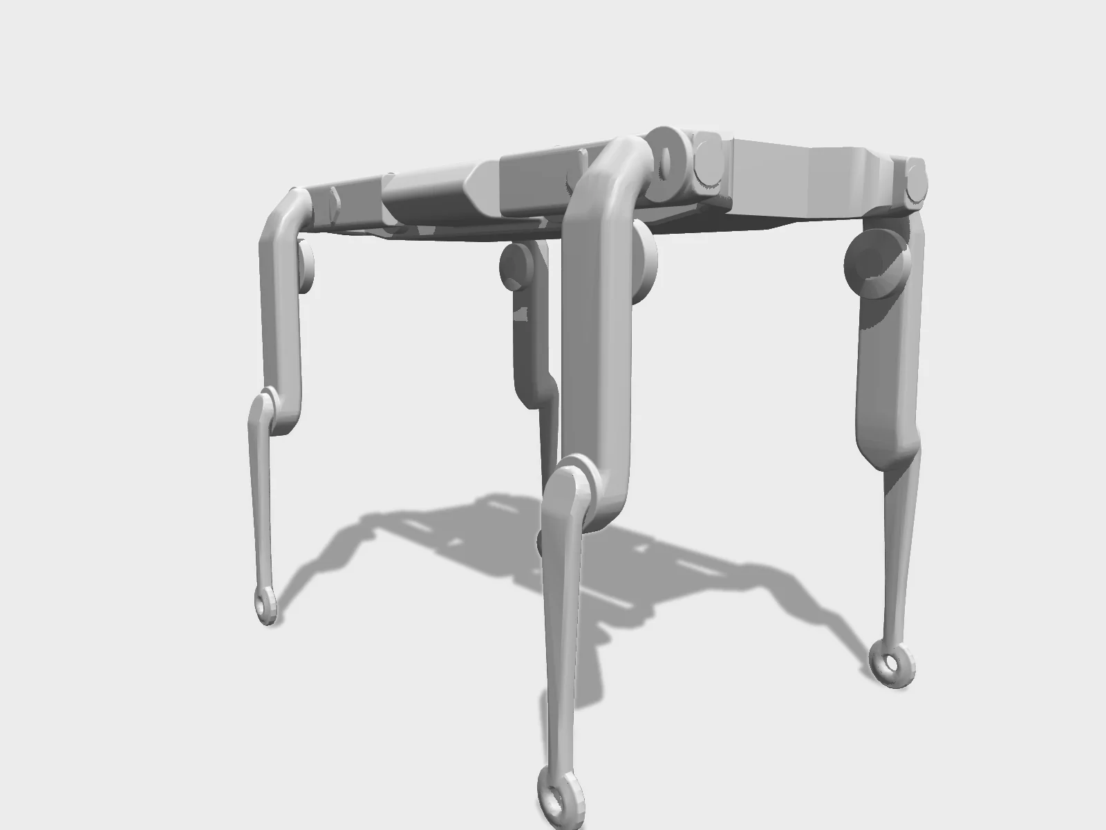
- Drawing
- /odri/solo-12
- Maker
- Open Dynamic Robot Initiative
- Country
- Tübingen, DE
- Package rev
- v0.1.0
- Level
- L1 Compiled
- Availability
- DIY
- Openness
- 90/100
- HW licence
- BSD-3-Clause
- Last checked
- 2026-09-25
- Mass
- 2.5 kg
- DOF
- 12
- Actuators
- ODRI open-source brushless torque-controlled actuator modules
Multi-institution academic initiative, so no single HQ given. Actuator/solo repos mostly unchanged since 2022-2023; master-board updated 2026. Mass 2.5 kg per the 12-DOF quadruped hardware README (v1, tethered); the v1.1 autonomy upgrade weighs 2.8 kg; 2.2 kg, quoted by some sources, is the Solo-8 figure. License mismatch upstream: the master-board README says BSD 2-Clause while its ordering page says BSD 3-Clause; actuator hardware and software are BSD-3-Clause.
Configure
Saved in the URL. Share the link to share the build.Source
One cart across 10 vendors · prices in USD as listed49 lines · 929 parts · 31 without an offer in US · 14/49 lines sourced in 2+ regions (L3 gate)
| # | Part | Category | Qty | Unit | Line | Offer |
|---|---|---|---|---|---|---|
SBN4 lines · unpriced | ||||||
| 1 | Output shaft bearing 32 x 25 x 4 mm, EZO 61705 2RS VA stainless (2 per module) structure.bearing-61705 · MPN 61705 2RS VA | structure | 24 | unpriced | — | SBNships globallyQuote by email to info@sbn.de, ships worldwide; SBN # C02748 |
| 2 | Motor and center shaft bearing 8 x 4 x 2 mm, EZO MR84 VA stainless (3 per module) structure.bearing-mr84 · MPN MR84 VA | structure | 36 | unpriced | — | SBNships globallyQuote by email to info@sbn.de, ships worldwide; SBN # N09724 |
| 3 | Belt tensioner bearing 7 x 3 x 3 mm, EZO 683 2Z VA stainless (2 per module) structure.bearing-683 · MPN 683 2Z VA · 1 alt | structure | 24 | unpriced | — | SBNships globallyQuote by email to info@sbn.de, ships worldwide; SBN # N05560 |
| 4 | Hip AA bearing 25 x 20 x 4 mm, ET2520 2Z VA stainless structure.bearing-hip-aa · MPN ET2520 2Z VA | structure | 4 | unpriced | — | SBNships globallyQuote by email to info@sbn.de, ships worldwide; SBN # C07024 |
McMaster-Carr4 lines · unpriced | ||||||
| 5 | Helicoil M3 x 6 insert, output pulley (2 per module; not installed in the 4 Hip AA pulleys) fastener.helicoil-m3x6 · MPN Böllhoff 41890030006 | fastener | 24 | unpriced | — | McMaster-CarrMcMaster 91732A773 |
| 6 | Motor phase wire LiY/LifY 0.50 mm² black, 100 m spool (also used for power and driver-side phase wires) cable.phase-wire-0p5 · MPN Kabeltronik 1601050 | cable | 1 | unpriced | — | McMaster-Carr |
| 7 | Helicoil M2.5 x 3.75 insert (27 per leg) fastener.helicoil-m2p5x3p75 · MPN Böllhoff 41890250375 | fastener | 108 | unpriced | — | McMaster-CarrMcMaster 91732A767 |
| 8 | Helicoil M3 x 4.5 insert (32 body structure + 8 calibration tools) fastener.helicoil-m3x4p5 · MPN Böllhoff 41890030045 | fastener | 40 | unpriced | — | McMaster-CarrMcMaster 91732A647 (calibration tool BOM) |
HobbyKing1 line · unpriced | ||||||
| 9 | 2 mm gold motor phase connectors, Reely RE-1373188 (3 per module) cable.phase-connector-2mm · MPN RE-1373188 | cable | 36 | unpriced | — | HobbyKingships globally10 pairs per set |
Kabeltronik1 line · unpriced | ||||||
| 10 | Encoder/SPI wire LifY 0.14 mm², red, yellow, black, white, green (100 m spools) cable.encoder-wire-0p14 · MPN Kabeltronik 1601014 | cable | 5 | unpriced | — | Kabeltronikships globallyShips worldwide |
RS Americas2 lines · unpriced | ||||||
| 11 | Hirose DF13-5S-1.25C 5-pin socket (encoder: 1 per module; SPI: 2 per wire x 6) cable.df13-5s · MPN DF13-5S-1.25C | cable | 24 | unpriced | — | RS AmericasRS 143-015 |
| 12 | Hirose DF13-2630SCF crimp terminal, 26-30 AWG (5 per 5-pin socket) cable.df13-crimp · MPN DF13-2630SCF · 1 alt | cable | 120 | unpriced | — | RS AmericasRS 503-8325 |
MacroFab1 line · unpriced | ||||||
| 13 | MicroDriver v2 dual brushless driver board (TI F28069M + DRV8305), 6 layers, 51 x 50 mm electronics.micro-driver | electronics | 6 | unpriced | — | MacroFabUsed successfully in the US per upstream; files in production_files/ |
Mouser1 line · unpriced | ||||||
| 14 | Precision resistor 7 mΩ ±1% CRE2512-FZ-R007E-3, phase current shunt (6 per micro driver) electronics.shunt-7mohm · MPN CRE2512-FZ-R007E-3 | electronics | 36 | unpriced | — | MouserMouser 652-CRE2512FZR007E-3 |
DigiKey2 lines · unpriced | ||||||
| 15 | Hirose DF13-5P-1.25DS(20) right-angle 5-pin header, encoder and SPI connectors on the micro drivers (count per board not stated; 2 encoders + 1 SPI each) electronics.df13-5p-ra · MPN DF13-5P-1.25DS(20) · 1 alt | electronics | 18 | unpriced | — | DigiKeyH2202-ND |
| 16 | Spectrum Digital XDS100V2 USB JTAG emulator + 1.27 mm 8-pin header, 2.54 mm header and ribbon cable (micro driver flashing) electronics.xds100v2 · MPN XDS100V2 | electronics | 1 | unpriced | — | DigiKey702302-ND; Farnell 1831927 |
MicroStrain1 line · unpriced | ||||||
| 17 | LORD MicroStrain 3DM-CX5-25 IMU, extended range (gyro ±900 deg/s, accel ±20 g) sensor.imu-3dm-cx5-25 · MPN 3DM-CX5-25 | sensor | 1 | unpriced | — | MicroStrainships globallyBuy through the distributors page (microstrain.com/support/distributors); no price |
Vicon distributors1 line · unpriced | ||||||
| 18 | Vicon marker 9.5 mm on plastic foot + M4 x 10 set screw each (optional, for the Vicon center plate) other.vicon-markers | other | 13 | unpriced | — | Vicon distributorsships globally |
No offer in this region31 lines · unpriced | ||||||
| 19 | T-Motor Antigravity 4004 300kV outrunner (1 per actuator module; sold in sets of 2) actuator.tmotor-4004 · MPN Antigravity 4004 300KV | actuator | 12 | unpriced | — | Offers in CN only |
| 20 | ODRI Encoder Kit v1.0 #109381: pre-assembled motor shaft with code wheel, aluminium 7075 center pulley, AEDT-9810-Z00 encoder head sensor.odri-encoder-kit · MPN 109381 · 2 alt | sensor | 12 | unpriced | — | Offers in EU only |
| 21 | Conti Synchroflex AT3 GEN III timing belt, 4 mm wide, 150 mm, 50 teeth (first stage) structure.belt-at3-150 · MPN Reiff 60047626 | structure | 12 | unpriced | — | Offers in EU only |
| 22 | Conti Synchroflex AT3 GEN III timing belt, 6 mm wide, 201 mm, 67 teeth (second stage) structure.belt-at3-201 · MPN Reiff 60005258 | structure | 12 | unpriced | — | Offers in EU only |
| 23 | M3 x 16 Phillips flat head screw, polyamide (encoder mount; 2 per module; Conrad sells 10 per set) fastener.m3x16-flat-pa · MPN Conrad 839967 | fastener | 24 | unpriced | — | Offers in EU only |
| 24 | M3 x 5 flat head screw, stainless (motor; 4 per module) fastener.m3x5-flat | fastener | 48 | unpriced | — | Offers in EU only |
| 25 | M3 x 10 flat head screw, stainless (belt tensioner; 2 per module) fastener.m3x10-flat | fastener | 24 | unpriced | — | Offers in EU only |
| 26 | M2.5 washer, stainless (belt tensioner; 2 per module) fastener.m2p5-washer | fastener | 24 | unpriced | — | Offers in EU only |
| 27 | M3 x 35 socket head, stainless: Hip AA to Hip FE with hip adapter (2 per leg on FR and HL) fastener.m3x35 | fastener | 4 | unpriced | — | Offers in EU only |
| 28 | M3 x 22 socket head, stainless: Hip AA to Hip FE without adapter (2 per leg on FL and HR) fastener.m3x22 | fastener | 4 | unpriced | — | Offers in EU only |
| 29 | M3 x 16 socket head, stainless (2 per leg; 8 more for the calibration tools) fastener.m3x16 | fastener | 16 | unpriced | — | Offers in EU only |
| 30 | M3 x 12 socket head, stainless (2 per leg + 16 for the body structure sides) fastener.m3x12 | fastener | 24 | unpriced | — | Offers in EU only |
| 31 | M3 washer, stainless (2 per leg) fastener.m3-washer | fastener | 8 | unpriced | — | No offer found yet |
| 32 | M2.5 x 6 socket head, stainless (12 per leg: shells) fastener.m2p5x6 | fastener | 48 | unpriced | — | Offers in EU only |
| 33 | M2.5 x 10 socket head, stainless (15 per leg + 16 for the Hip AA modules on the body) fastener.m2p5x10 | fastener | 76 | unpriced | — | Offers in EU only |
| 34 | Bicycle tire for the feet, e.g. Schwalbe Lugano 28" 23-622, cut into 75 x 7 mm strips (1 per foot) other.bicycle-tire | other | 1 | unpriced | — | No offer found yet |
| 35 | Master Board v2 (ESP32; SPI to up to 8 micro drivers, Ethernet/Wi-Fi to PC at 1 kHz) electronics.master-board | electronics | 1 | unpriced | — | Offers in EU only |
| 36 | HanRun RJ45 jack HR911105A for the master board (hand-soldered) electronics.ethernet-jack · MPN HR911105A | electronics | 1 | unpriced | — | Offers in EU only |
| 37 | WS2812B-type 5050 NeoPixel LED for master board status (2 per board, optional) electronics.neopixel | electronics | 2 | unpriced | — | Offers in EU only |
| 38 | Right-angle 2.54 mm pin header for motor phase and power on the micro drivers electronics.pin-header-ra | electronics | 6 | unpriced | — | Offers in EU only |
| 39 | IMU ribbon cable Samtec FFSD-05-S-06-00-01-N (10-pin) with extension wires to a 4-pin DF13 on UART1 cable.imu · MPN FFSD-05-S-06-00-01-N | cable | 1 | unpriced | — | Offers in EU only |
| 40 | M3 x 8 socket head, stainless (body structure center) fastener.m3x8 | fastener | 8 | unpriced | — | Offers in EU only |
| 41 | M3 x 14 socket head, stainless (Hip AA supports) fastener.m3x14 | fastener | 8 | unpriced | — | Offers in EU only |
| 42 | M2.5 x 25 socket head, stainless (micro driver stacks) fastener.m2p5x25 | fastener | 8 | unpriced | — | Offers in EU only |
| 43 | M2.5 x 16 slotted screw, polyamide, shortened to 13 mm (IMU) fastener.m2p5x16-pa · MPN Conrad 839940-62 | fastener | 3 | unpriced | — | Offers in EU only |
| 44 | Lab power supply VOLTCRAFT DPPS-32-20 (1-32 V, 0-20 A, 230 V input); robots run at 24 V power.lab-psu · MPN DPPS-32-20 | power | 1 | unpriced | — | Offers in EU only |
| 45 | XT30U plug and receptacle (Reely RE-6619104 / RE-6619107), robot-side power cable.xt30 | cable | 1 | unpriced | — | Offers in EU only |
| 46 | Robot interface cable: 1 mm² power pair with 4 mm supply-side plugs, plus Ethernet (standard cable or self-made 4-pole with RJ45 Cat5e plugs, RS 821-2949) cable.tether | cable | 1 | unpriced | — | No offer found yet |
| 47 | USB-serial adapter with RTS/DTR for the master board PROG connector (upstream uses an ESP32 dev board with its module removed) electronics.esp-programmer | electronics | 1 | unpriced | — | No offer found yet |
| 48 | Stainless dowel pins for the calibration tools: 8 x (2 x 16 mm) and 8 x (2.5 x 12 mm) other.calibration-pins | other | 16 | unpriced | — | Offers in EU only |
| 49 | Robot stand: item 40x40 size 8 slotted profile, 2 x 40 cm vertical + 1 x 35 cm horizontal, 4 angle brackets 0.0.411.15, 2 M8x25 flat head, 8 M5x20, 4 rubber feet (RS 173-5948) structure.stand-profiles | structure | 1 | unpriced | — | Offers in EU only |
| Cart total · US | 929 | $0.00 | 49 lines unpriced, not in total | |||
Fabricate
Planned for a 256 mm bed- Fabricated parts
- 161
- Print time (sum)
- —
- Material (sum)
- 1,080 g
- Plates · estimate
- ≈ 2
Plates is an estimate, not a slice: the package has no part footprints, so it assumes about 200 g of FDM parts per plate on a 256 mm bed, scaled by bed area (256 mm ≈ 200 g/plate). Parts larger than your bed are not detected.
| Part | Process | Material | Qty | h / part | g / part | Profile |
|---|---|---|---|---|---|---|
Transmission pulley AT3 T30 center (press-fit onto the 10-tooth aluminium pulley) sla.pulley-center | SLA | VisiJet M3X (Projet multijet) or Accura Extreme Grey SLA | 12 | — | 4 | High-detail SLA/multijet/polyjet, print in +Z of the STL; tooth profile must be precise and concentric |
Transmission pulley AT3 T30 output sla.pulley-output | SLA | VisiJet M3X or Accura Extreme Grey SLA | 12 | — | 7 | High-detail SLA/multijet/polyjet, +Z; bearing diameters printed oversize and turned on a lathe |
Belt tensioner roller 10.0 mm (9.0-11.5 mm variants adjust belt tension) sla.tensioner-roller | SLA | VisiJet M3X or Accura Extreme Grey SLA | 24 | — | 0 | High-detail SLA/multijet/polyjet, +Z |
Motor pulley AT3 T10, aluminium (only without the ODRI Encoder Kit) cnc.motor-pulley | CNC | Aluminium 7075 | 12 | — | 1 | Modified AT3 profile: custom form cutter per pulley_at3_t10_form_cutter.PDF (3 mm shank, 3 teeth, 20° helix), then lathe; do not use standard AT3 tools |
Center pulley AT3 T10, aluminium (only without the ODRI Encoder Kit) cnc.center-pulley | CNC | Aluminium 7075 | 12 | — | 2 | Same form cutter route as the motor pulley; drawing center_pulley_at3_t10.PDF |
Motor shaft, 4 mm stainless (only without the ODRI Encoder Kit) cnc.motor-shaft | CNC | Stainless 1.4301 h9 4.0 mm ground rod | 12 | — | 3 | Lathe per motor_shaft.PDF; stock 3.97-3.99 mm fits the bearings as-is |
Hip AA module shell base sls.hip-aa-base | SLS | Duraform HST (3D Systems) or PC-ABS FDM solid | 4 | — | 21 | SLS in +Z (orientation must be fixed via 3D Systems engineering support), or Fortus FDM PC-ABS, T12 nozzle, 0.178 mm, solid interior |
Hip AA module shell cover sls.hip-aa-cover | SLS | Duraform HST or PC-ABS FDM solid | 4 | — | 16 | As hip AA base |
Hip FE module shell base (alt_a version simplifies wire routing) sls.hip-fe-base | SLS | Duraform HST or PC-ABS FDM solid | 4 | — | 25 | As hip AA base |
Hip FE module shell cover sls.hip-fe-cover | SLS | Duraform HST or PC-ABS FDM solid | 4 | — | 16 | As hip AA base |
Upper leg module shell base sls.upper-leg-base | SLS | Duraform HST or PC-ABS FDM solid | 4 | — | 27 | As hip AA base |
Upper leg module shell cover sls.upper-leg-cover | SLS | Duraform HST or PC-ABS FDM solid | 4 | — | 15 | As hip AA base |
Lower leg v2 (FDM sparse double dense) or v3 (solid SLS/FDM); 160 mm knee to foot fdm.lower-leg | FDM | PC-ABS | 4 | — | 20 | v2: Fortus 'sparse double dense'; v3: solid |
Body structure back fdm.body-back | FDM | PC-ABS (Fortus) or SLS | 1 | — | 12 | Standard solid interior, +Z |
Body structure bottom Rev A (for right-angle Hirose micro driver connectors) fdm.body-bottom | FDM | PC-ABS (Fortus) or SLS | 2 | — | 10 | Standard solid interior, +Z |
Body structure center (top or bottom) fdm.body-center | FDM | PC-ABS (Fortus) or SLS | 1 | — | 24 | Standard solid interior, +Z |
Body structure center with handle fdm.body-center-handle | FDM | PC-ABS (Fortus) or SLS | 1 | — | 29 | Standard solid interior, +Z |
Body structure center with Vicon marker mounts (optional) fdm.body-center-vicon | FDM | PC-ABS (Fortus) or SLS | 1 | — | 30 | Standard solid interior, +Z |
Body structure front fdm.body-front | FDM | PC-ABS (Fortus) or SLS | 1 | — | 12 | Standard solid interior, +Z |
Body structure Hip AA support (Rev A on the page, plain file in the BOM table) fdm.hip-aa-support | FDM | PC-ABS (Fortus) or SLS | 4 | — | 20 | Standard solid interior, +Z; bearing seat opened with a 25 mm end mill if tight |
Body structure side fdm.body-side | FDM | PC-ABS (Fortus) or SLS | 4 | — | 18 | Standard solid interior, +Z |
Body structure top IMU fdm.body-top-imu | FDM | PC-ABS (Fortus) or SLS | 1 | — | 12 | Standard solid interior, +Z |
Body structure top master board fdm.body-top-mb | FDM | PC-ABS (Fortus) or SLS | 1 | — | 11 | Standard solid interior, +Z |
LED cover fdm.led-cover | FDM | Transparent or translucent | 1 | — | 0 | +Z |
Hip adapter (front right and hind left legs) fdm.hip-adapter | FDM | PC-ABS (Fortus) or SLS | 2 | — | 5 | Standard solid interior, +Z |
Micro driver stack spacer fdm.stack-spacer | FDM | PC-ABS (Fortus) or SLS | 16 | — | 0 | +Z |
Calibration tool quadruped 12dof v1 fdm.calib-tool | FDM | PC-ABS | 2 | — | — | Fortus 'sparse double dense' |
Calibration tool quadruped 12dof v1, mirrored fdm.calib-tool-mirror | FDM | PC-ABS | 2 | — | — | Fortus 'sparse double dense' |
Calibration tool 12dof v1 connector fdm.calib-connector | FDM | PC-ABS | 2 | — | — | Solid |
Pin spacer tool 4 mm fdm.pin-spacer | FDM | PC-ABS | 1 | — | — | source |
Stand fork fdm.stand-fork | FDM | PC-ABS | 2 | — | — | Standard solid interior |
Stand foot fdm.stand-foot | FDM | PC-ABS | 4 | — | — | Standard solid interior |
Assemble
Every step ends in a check- Steps
- 21
- Subassemblies
- 7
- Hands-on time (sum)
- —
- Critical path
- —
- Your progress · this device
- —
21 steps have no time estimate; times above are lower bounds.
Steps, in build order
- Electronics prep01
Order the micro drivers and master board
Email info.de@beta-layout.com to replicate MicroDriver v2 order AU-201909/38760 (x6, plus spares) and Master Board v2 quote AN5eea24ae72697 (x1). Beta LAYOUT quotes boards plus placement, then sends the component list with prices for approval. In the US, MacroFab has built the micro drivers from the production files.
CHECK6 micro drivers arrive populated except the 6 shunt resistors and Hirose connectors; the master board arrives without the Ethernet jack and NeoPixels.- Parts in
- MicroDriver v2 dual brushless driver board (TI F28069M + DRV8305), 6 layers, 51 x 50 mmelectronics.micro-driver
- Master Board v2 (ESP32; SPI to up to 8 micro drivers, Ethernet/Wi-Fi to PC at 1 kHz)electronics.master-board
- Tools
- —
- Torque
- —
- Time
- —
- After
- Start
- Source
- github.com
- Fabrication02
Order encoder kits, precision prints and SLS shells
Get 12 ODRI Encoder Kits from PWB by email quote (or machine the motor pulley, center pulley and shaft yourself from the PDF drawings with a custom form cutter). Pulleys and rollers: SLA Accura Extreme Grey or multijet M3X. Shells: SLS Duraform HST through 3D Systems On Demand; save the order online, then email their engineering support with the order number to fix the print direction to +Z (auto-placement can make parts unusable).
CHECKPulley teeth are crisp and concentric; shell bearing seats measure close to nominal (25/32 mm) and the parts are flat.- Parts in
- ODRI Encoder Kit v1.0 #109381: pre-assembled motor shaft with code wheel, aluminium 7075 center pulley, AEDT-9810-Z00 encoder headsensor.odri-encoder-kit
- Transmission pulley AT3 T30 center (press-fit onto the 10-tooth aluminium pulley)sla.pulley-center
- Transmission pulley AT3 T30 outputsla.pulley-output
- Belt tensioner roller 10.0 mm (9.0-11.5 mm variants adjust belt tension)sla.tensioner-roller
- Hip AA module shell basesls.hip-aa-base
- Hip AA module shell coversls.hip-aa-cover
- Hip FE module shell base (alt_a version simplifies wire routing)sls.hip-fe-base
- Hip FE module shell coversls.hip-fe-cover
- Upper leg module shell basesls.upper-leg-base
- Upper leg module shell coversls.upper-leg-cover
- Motor pulley AT3 T10, aluminium (only without the ODRI Encoder Kit)cnc.motor-pulley
- Center pulley AT3 T10, aluminium (only without the ODRI Encoder Kit)cnc.center-pulley
- Motor shaft, 4 mm stainless (only without the ODRI Encoder Kit)cnc.motor-shaft
- Tools
- —
- Torque
- —
- Time
- —
- After
- Start
- Source
- github.com
- 03
Print body structure, lower legs, calibration tools and stand
Print everything in +Z of the STL. Body parts solid interior; lower legs v2 and calibration tools 'sparse double dense' (or lower leg v3 solid). LED cover in a translucent material.
CHECKAll body parts per the BOM counts, including 2 hip adapters and 16 stack spacers; no warping on the side and bottom plates.- Parts in
- Lower leg v2 (FDM sparse double dense) or v3 (solid SLS/FDM); 160 mm knee to footfdm.lower-leg
- Body structure backfdm.body-back
- Body structure bottom Rev A (for right-angle Hirose micro driver connectors)fdm.body-bottom
- Body structure center (top or bottom)fdm.body-center
- Body structure center with handlefdm.body-center-handle
- Body structure center with Vicon marker mounts (optional)fdm.body-center-vicon
- Body structure frontfdm.body-front
- Body structure Hip AA support (Rev A on the page, plain file in the BOM table)fdm.hip-aa-support
- Body structure sidefdm.body-side
- Body structure top IMUfdm.body-top-imu
- Body structure top master boardfdm.body-top-mb
- LED coverfdm.led-cover
- Hip adapter (front right and hind left legs)fdm.hip-adapter
- Micro driver stack spacerfdm.stack-spacer
- Calibration tool quadruped 12dof v1fdm.calib-tool
- Calibration tool quadruped 12dof v1, mirroredfdm.calib-tool-mirror
- Calibration tool 12dof v1 connectorfdm.calib-connector
- Pin spacer tool 4 mmfdm.pin-spacer
- Stand forkfdm.stand-fork
- Stand footfdm.stand-foot
- Tools
- FDM printer (upstream: Fortus, PC-ABS, T12 nozzle, 0.178 mm slices)
- Torque
- —
- Time
- —
- After
- Start
- Source
- github.com
- Actuators04
Prepare the 12 motors
Separate rotor and stator (the retaining ring can be sacrificed). Press the original shaft out of the rotor and ream the rotor bore to fit the 4 mm custom shaft without play. Strip the phase insulation, shorten the phase leads, solder the 0.5 mm² extension wires and the 2 mm gold connectors.
CHECKRotor slides onto the new shaft with a snug fit and does not wobble when spun; three phase leads end in 2 mm gold connectors.- Parts in
- T-Motor Antigravity 4004 300kV outrunner (1 per actuator module; sold in sets of 2)actuator.tmotor-4004
- Motor phase wire LiY/LifY 0.50 mm² black, 100 m spool (also used for power and driver-side phase wires)cable.phase-wire-0p5
- 2 mm gold motor phase connectors, Reely RE-1373188 (3 per module)cable.phase-connector-2mm
- Tools
- 3 mm pin punch and hammer, Reamers 3.98/3.99 mm, Soldering iron
- Torque
- —
- Time
- —
- After
- Start
- Source
- github.com
- 05
Encoder wiring (and modification if not using the kit)
The ODRI kit comes with the encoder head already modified and the shaft/codewheel bonded. Solder red, yellow, black, white and green 0.14 mm² extension wires to the encoder pins and crimp them into a 5-pin DF13 socket per the wiring convention. v1 route: first modify the encoder mounting holes and bond the codewheel to the machined shaft.
CHECKEach encoder has a 5-pin DF13 plug in the documented colour order; continuity checks pin to pin.- Parts in
- ODRI Encoder Kit v1.0 #109381: pre-assembled motor shaft with code wheel, aluminium 7075 center pulley, AEDT-9810-Z00 encoder headsensor.odri-encoder-kit
- Encoder/SPI wire LifY 0.14 mm², red, yellow, black, white, green (100 m spools)cable.encoder-wire-0p14
- Hirose DF13-5S-1.25C 5-pin socket (encoder: 1 per module; SPI: 2 per wire x 6)cable.df13-5s
- Hirose DF13-2630SCF crimp terminal, 26-30 AWG (5 per 5-pin socket)cable.df13-crimp
- Tools
- Hirose DF13 crimp tool DF13-TB2630HC (RS 503-8331), Countersink 90° 8 mm (v1 route)
- Torque
- —
- Time
- —
- After
- Start
- Source
- github.com
- Software06
Build the host software and prepare the Ethernet interface
`pip install treep`, clone `git@github.com:machines-in-motion/treep_machines_in_motion.git` into ~/devel, then `treep --clone master-board` and `treep --clone odri_control_interface` (or `treep --clone SOLO`), and `colcon build`. Connect the robot directly to a spare Ethernet port; optionally `sudo ifconfig <iface> -arp` and disable IPv6 on it. Put your interface name in `config_solo12.yaml` (odri_control_interface/demos) and rebuild.
CHECK`colcon build` succeeds and `ip a` shows the interface you set in the yaml.- Parts in
- Robot interface cable: 1 mm² power pair with 4 mm supply-side plugs, plus Ethernet (standard cable or self-made 4-pole with RJ45 Cat5e plugs, RS 821-2949)cable.tether
- Tools
- Ubuntu PC with a dedicated Ethernet port, treep, colcon
- Torque
- —
- Time
- —
- After
- Start
- Source
- github.com
- 07
Optional: load Solo12 in PyBullet
Install bullet_utils and robot_properties_solo with `pip3 install .` in each clone, then in Python: `env = BulletEnvWithGround(p.GUI)` and `robot = env.add_robot(Solo12Robot)` (from robot_properties_solo.solo12wrapper). The URDF comes from `resources/xacro/solo12.urdf.xacro`.
CHECKA PyBullet window shows Solo12 standing on the ground plane.- Parts in
- —
- Tools
- Pinocchio (`conda install -c conda-forge pinocchio`), bullet_utils
- Torque
- —
- Time
- —
- After
- Start
- Source
- github.com
- Electronics prep08
Solder shunts and connectors on the micro drivers
Solder the six 7 mΩ shunt resistors on the back of each board (tack one end, solder the other, then finish the first). Fit right-angle DF13 headers on the bottom side (straight ones go on the top) for encoders and SPI, and the right-angle 2.54 mm headers for motor phases and power.
CHECKSix shunts per board with full fillets and no bridges; DF13 headers on the correct side so the pinout matches the actuator wiring convention.- Parts in
- MicroDriver v2 dual brushless driver board (TI F28069M + DRV8305), 6 layers, 51 x 50 mmelectronics.micro-driver
- Precision resistor 7 mΩ ±1% CRE2512-FZ-R007E-3, phase current shunt (6 per micro driver)electronics.shunt-7mohm
- Hirose DF13-5P-1.25DS(20) right-angle 5-pin header, encoder and SPI connectors on the micro drivers (count per board not stated; 2 encoders + 1 SPI each)electronics.df13-5p-ra
- Right-angle 2.54 mm pin header for motor phase and power on the micro driverselectronics.pin-header-ra
- Tools
- Fine-tip soldering iron, Flux, Magnifier
- Torque
- —
- Time
- —
- After
- 01
- Source
- github.com
- 09
Solder, fuse and flash the master board
Safety · human-verified requiredSolder the RJ45 jack and the NeoPixels. Install esp-idf (`git clone -b v4.0.1 --recursive https://github.com/espressif/esp-idf.git`, `./install.sh`, `pip install esptool`), add yourself to `dialout`. Power the board (5-30 V), connect the programmer to PROG. On a fresh board only, once: `espefuse.py set_flash_voltage 3.3V` (irreversible). In esp-idf `git checkout 8d1a9c0` and `git submodule update --init --recursive`; then in master-board/firmware `source setup_esp_idf.bash` and `make flash`.
CHECKFlash completes; on power-up the NeoPixel shows red fade (waiting for init), then magenta (SPI autodetect) once drivers are attached.This step can hurt a person or ruin parts. Its instructions need sign-off by a human who has done it before relying on them. Stop and ask if anything differs from what you see.
- Parts in
- Master Board v2 (ESP32; SPI to up to 8 micro drivers, Ethernet/Wi-Fi to PC at 1 kHz)electronics.master-board
- HanRun RJ45 jack HR911105A for the master board (hand-soldered)electronics.ethernet-jack
- WS2812B-type 5050 NeoPixel LED for master board status (2 per board, optional)electronics.neopixel
- USB-serial adapter with RTS/DTR for the master board PROG connector (upstream uses an ESP32 dev board with its module removed)electronics.esp-programmer
- Lab power supply VOLTCRAFT DPPS-32-20 (1-32 V, 0-20 A, 230 V input); robots run at 24 Vpower.lab-psu
- Tools
- Soldering iron, Linux PC with esp-idf v4.0.1 install script, rolled back to commit 8d1a9c0
- Torque
- —
- Time
- —
- After
- 01
- Source
- github.com
- Actuators10
Center pulley press-fit, tensioners, output pulley
Press the 30-tooth printed pulley onto the 10-tooth aluminium center pulley with the arbor press and the printed tools. Fit 683 bearings in the tensioner rollers. Turn the output pulley's bearing diameters to size on the lathe. Drill its two holes up in 0.1 mm steps to 3.3 mm and install M3x6 Helicoils, except on the 4 Hip AA pulleys: open those holes to 3 mm and fit no inserts.
CHECKCenter pulley assembly runs true; output pulley slides into the 61705 bearings with a light press fit; 4 Hip AA pulleys have plain 3 mm holes.- Parts in
- Transmission pulley AT3 T30 center (press-fit onto the 10-tooth aluminium pulley)sla.pulley-center
- Transmission pulley AT3 T30 outputsla.pulley-output
- Belt tensioner roller 10.0 mm (9.0-11.5 mm variants adjust belt tension)sla.tensioner-roller
- Belt tensioner bearing 7 x 3 x 3 mm, EZO 683 2Z VA stainless (2 per module)structure.bearing-683
- Helicoil M3 x 6 insert, output pulley (2 per module; not installed in the 4 Hip AA pulleys)fastener.helicoil-m3x6
- ODRI Encoder Kit v1.0 #109381: pre-assembled motor shaft with code wheel, aluminium 7075 center pulley, AEDT-9810-Z00 encoder headsensor.odri-encoder-kit
- Tools
- Arbor press, Printed tools tool_center_pulley_protection / tool_center_pulley_assembly, Lathe, M3 Helicoil tool set (Hoffmann 082800 M3), Drill set in 0.1 mm steps
- Torque
- —
- Time
- —
- After
- 02
- Source
- github.com
- 11
Prepare the shells: threads, Helicoils, bearing seats
Check flatness and through-hole diameters. Cut the M3 threads all the way through. Tap and install the M2.5 Helicoils, stopping when the tap bottoms out (printed threads strip easily). Open tight bearing seats with the end mills until the bearings press in and out by hand with moderate force (no reamers). Fit the 61705 and MR84 bearings and test-mount base and cover with the 8 M2.5 screws.
CHECKBearings seat by hand with a light press fit and do not fall out; base and cover close flat.- Parts in
- Hip AA module shell basesls.hip-aa-base
- Hip AA module shell coversls.hip-aa-cover
- Hip FE module shell base (alt_a version simplifies wire routing)sls.hip-fe-base
- Hip FE module shell coversls.hip-fe-cover
- Upper leg module shell basesls.upper-leg-base
- Upper leg module shell coversls.upper-leg-cover
- Helicoil M2.5 x 3.75 insert (27 per leg)fastener.helicoil-m2p5x3p75
- Output shaft bearing 32 x 25 x 4 mm, EZO 61705 2RS VA stainless (2 per module)structure.bearing-61705
- Motor and center shaft bearing 8 x 4 x 2 mm, EZO MR84 VA stainless (3 per module)structure.bearing-mr84
- M2.5 x 6 socket head, stainless (12 per leg: shells)fastener.m2p5x6
- M2.5 x 10 socket head, stainless (15 per leg + 16 for the Hip AA modules on the body)fastener.m2p5x10
- Tools
- M3 tap (Hoffmann 131300 M3), M2.5 and M3 Helicoil tool sets, End mills 8 mm and 32 mm with dulled bottom edges
- Torque
- —
- Time
- —
- After
- 02
- Source
- github.com
- Body12
Prepare the body structure
Tap the M2.5 holes in the micro driver and IMU supports (M4 for the Vicon plate), install the 32 M3x4.5 Helicoils, and open the Hip AA support seats with the 25 mm end mill until the ET2520 bearings press in by hand. Follow the five preparation drawings on the Solo12 page.
CHECKAll Helicoils flush; the 4 hip AA bearings seated and spinning freely.- Parts in
- Body structure backfdm.body-back
- Body structure bottom Rev A (for right-angle Hirose micro driver connectors)fdm.body-bottom
- Body structure frontfdm.body-front
- Body structure Hip AA support (Rev A on the page, plain file in the BOM table)fdm.hip-aa-support
- Body structure sidefdm.body-side
- Body structure top IMUfdm.body-top-imu
- Body structure top master boardfdm.body-top-mb
- Body structure center (top or bottom)fdm.body-center
- Helicoil M3 x 4.5 insert (32 body structure + 8 calibration tools)fastener.helicoil-m3x4p5
- Hip AA bearing 25 x 20 x 4 mm, ET2520 2Z VA stainlessstructure.bearing-hip-aa
- Tools
- M2.5 and M4 taps, M3 Helicoil tool set, 25 mm end mill
- Torque
- —
- Time
- —
- After
- 03
- Source
- github.com
- Electronics prep13
Build and flash the SPI firmware on each micro driver
Safety · human-verified required`git clone --recursive https://github.com/open-dynamic-robot-initiative/udriver_firmware.git`. Copy MotorWare's `sw` tree into `firmware/firmware_spi/motorware` and run `patch -p1 < ../motorware_1_01_00_18.patch` there. Import `mw_dual_motor_torque_ctrl` into CCS (do not copy into workspace). Default config targets the Antigravity 4004 300kV. Power the board from the lab supply (current-limited), connect the XDS100V2 with a ~10 cm cable, select the 'Flash' build and run the debugger to write flash.
CHECKCCS writes flash without error; after a power cycle the board's green/blue LED is on (system enabled) and the red error LED is off.This step can hurt a person or ruin parts. Its instructions need sign-off by a human who has done it before relying on them. Stop and ask if anything differs from what you see.
- Parts in
- MicroDriver v2 dual brushless driver board (TI F28069M + DRV8305), 6 layers, 51 x 50 mmelectronics.micro-driver
- Spectrum Digital XDS100V2 USB JTAG emulator + 1.27 mm 8-pin header, 2.54 mm header and ribbon cable (micro driver flashing)electronics.xds100v2
- Lab power supply VOLTCRAFT DPPS-32-20 (1-32 V, 0-20 A, 230 V input); robots run at 24 Vpower.lab-psu
- Tools
- TI Code Composer Studio (tested 9.1.0, C2000 support + TI XDS probes), TI MotorWare 1.01.00.18
- Torque
- —
- Time
- —
- After
- 08
- Actuators14
Assemble 12 actuator modules
Mount the stator with 4 M3x5 flat heads, install the motor shaft and rotor, the 150 mm (first stage) and 201 mm (second stage) belts, the encoder with 2 M3x16 polyamide flat heads, and the tensioner rollers (M3x10 flat head + M2.5 washer each). Close the shell (upstream: 5 M2.5x6 + 3 M2.5x8). Route out the 3 phase leads and the encoder plug.
CHECKOutput turns smoothly by hand through the 9:1 drive with no skipped teeth or belt rubbing; backlash is barely perceptible.- Parts in
- T-Motor Antigravity 4004 300kV outrunner (1 per actuator module; sold in sets of 2)actuator.tmotor-4004
- ODRI Encoder Kit v1.0 #109381: pre-assembled motor shaft with code wheel, aluminium 7075 center pulley, AEDT-9810-Z00 encoder headsensor.odri-encoder-kit
- Conti Synchroflex AT3 GEN III timing belt, 4 mm wide, 150 mm, 50 teeth (first stage)structure.belt-at3-150
- Conti Synchroflex AT3 GEN III timing belt, 6 mm wide, 201 mm, 67 teeth (second stage)structure.belt-at3-201
- M3 x 5 flat head screw, stainless (motor; 4 per module)fastener.m3x5-flat
- M3 x 16 Phillips flat head screw, polyamide (encoder mount; 2 per module; Conrad sells 10 per set)fastener.m3x16-flat-pa
- M3 x 10 flat head screw, stainless (belt tensioner; 2 per module)fastener.m3x10-flat
- M2.5 washer, stainless (belt tensioner; 2 per module)fastener.m2p5-washer
- M2.5 x 6 socket head, stainless (12 per leg: shells)fastener.m2p5x6
- M2.5 x 10 socket head, stainless (15 per leg + 16 for the Hip AA modules on the body)fastener.m2p5x10
- Tools
- Wiha PicoFinish hex and Phillips drivers, Loctite
- Torque
- —
- Time
- —
- Source
- github.com
- 15
Bench-test each module on a micro driver
Safety · human-verified requiredConnect a module's phases and encoder to a flashed micro driver, SPI to the master board, 24 V from the current-limited lab supply. Clamp the module. On first enable the firmware runs a motor alignment: the rotor moves slightly and holds for a few seconds; keep the output unloaded and do not touch it. Then run the SDK example (`sudo ./bin/exec <iface>` with N_CONTROLLED_SLAVE set) to drive a sinusoid.
CHECKDriver LED goes from fast blinking (aligning) to slow blinking (motor enabled) with no red LED; the output follows the sinusoid smoothly and the encoder index is found.This step can hurt a person or ruin parts. Its instructions need sign-off by a human who has done it before relying on them. Stop and ask if anything differs from what you see.
- Parts in
- MicroDriver v2 dual brushless driver board (TI F28069M + DRV8305), 6 layers, 51 x 50 mmelectronics.micro-driver
- Master Board v2 (ESP32; SPI to up to 8 micro drivers, Ethernet/Wi-Fi to PC at 1 kHz)electronics.master-board
- Lab power supply VOLTCRAFT DPPS-32-20 (1-32 V, 0-20 A, 230 V input); robots run at 24 Vpower.lab-psu
- Tools
- Linux PC with the master-board SDK (see host-setup)
- Torque
- —
- Time
- —
- Body16
Micro driver stacks, master board, IMU and wiring
Build front and back stacks of 3 micro drivers each with the printed spacers and M2.5x25 screws; driver-side phase wires 8 cm, power wires 25 cm (front) / 15 cm (back) with XT30. Crimp SPI wires: 30 cm to the front stack (0-AA, 1-FL, 2-FR), 14 cm to the back (3-AA, 4-HL, 5-HR). Mount the IMU at the front, label down, with 3 polyamide M2.5 screws cut to 13 mm; IMU wire 35 cm to UART1. Follow the motor assignment table (e.g. FL_HFE on card 1 port 1).
CHECKEvery driver card and port matches the joint table; SPI plugs in the right master board sockets; the IMU label faces down.- Parts in
- MicroDriver v2 dual brushless driver board (TI F28069M + DRV8305), 6 layers, 51 x 50 mmelectronics.micro-driver
- Micro driver stack spacerfdm.stack-spacer
- M2.5 x 25 socket head, stainless (micro driver stacks)fastener.m2p5x25
- Master Board v2 (ESP32; SPI to up to 8 micro drivers, Ethernet/Wi-Fi to PC at 1 kHz)electronics.master-board
- LORD MicroStrain 3DM-CX5-25 IMU, extended range (gyro ±900 deg/s, accel ±20 g)sensor.imu-3dm-cx5-25
- IMU ribbon cable Samtec FFSD-05-S-06-00-01-N (10-pin) with extension wires to a 4-pin DF13 on UART1cable.imu
- M2.5 x 16 slotted screw, polyamide, shortened to 13 mm (IMU)fastener.m2p5x16-pa
- Motor phase wire LiY/LifY 0.50 mm² black, 100 m spool (also used for power and driver-side phase wires)cable.phase-wire-0p5
- Encoder/SPI wire LifY 0.14 mm², red, yellow, black, white, green (100 m spools)cable.encoder-wire-0p14
- Hirose DF13-5S-1.25C 5-pin socket (encoder: 1 per module; SPI: 2 per wire x 6)cable.df13-5s
- Hirose DF13-2630SCF crimp terminal, 26-30 AWG (5 per 5-pin socket)cable.df13-crimp
- XT30U plug and receptacle (Reely RE-6619104 / RE-6619107), robot-side powercable.xt30
- LED coverfdm.led-cover
- Tools
- DF13 crimp tool, Soldering iron
- Torque
- —
- Time
- —
- Source
- github.com
- Legs17
Assemble 4 legs (Hip AA, Hip FE, upper leg modules + lower leg)
Line each lower leg's foot with a 75 x 7 mm bicycle tire strip. Join the Hip AA module to the Hip FE module: with the hip adapter and M3x35 on the front-right and hind-left legs, without adapter and M3x22 on the other two. Fit the upper leg module and the lower leg. Optionally fit the upper-leg stopper (printed + 10 mm silicone tube) to stop multi-turn wind-up.
CHECKFour legs; adapters on FR and HL only; Hip FE and knee turn freely (they can do multiple turns, limited only by wiring).- Parts in
- Lower leg v2 (FDM sparse double dense) or v3 (solid SLS/FDM); 160 mm knee to footfdm.lower-leg
- Bicycle tire for the feet, e.g. Schwalbe Lugano 28" 23-622, cut into 75 x 7 mm strips (1 per foot)other.bicycle-tire
- Hip adapter (front right and hind left legs)fdm.hip-adapter
- M3 x 35 socket head, stainless: Hip AA to Hip FE with hip adapter (2 per leg on FR and HL)fastener.m3x35
- M3 x 22 socket head, stainless: Hip AA to Hip FE without adapter (2 per leg on FL and HR)fastener.m3x22
- M3 x 16 socket head, stainless (2 per leg; 8 more for the calibration tools)fastener.m3x16
- M3 x 12 socket head, stainless (2 per leg + 16 for the body structure sides)fastener.m3x12
- M3 washer, stainless (2 per leg)fastener.m3-washer
- M2.5 x 10 socket head, stainless (15 per leg + 16 for the Hip AA modules on the body)fastener.m2p5x10
- Tools
- Hex drivers, Cutter for the tire strips
- Torque
- —
- Time
- —
- Source
- github.com
- Body18
Mount the legs and close the body
Fix the Hip AA modules to the body with 16 M2.5x10, the Hip AA supports with 8 M3x14, the sides with 16 M3x12 and the center plates with 8 M3x8 (swap in the Vicon center plate with its 13 markers on M4x10 set screws if you use motion capture). Route phase and encoder wires per the wiring page (lengths per joint are tabulated there) and plug each module into its driver port.
CHECKHips abduct through their range (215° standard) without pulling any wire; all 12 encoder and 36 phase plugs are connected.- Parts in
- M2.5 x 10 socket head, stainless (15 per leg + 16 for the Hip AA modules on the body)fastener.m2p5x10
- M3 x 14 socket head, stainless (Hip AA supports)fastener.m3x14
- M3 x 12 socket head, stainless (2 per leg + 16 for the body structure sides)fastener.m3x12
- M3 x 8 socket head, stainless (body structure center)fastener.m3x8
- Body structure center with handlefdm.body-center-handle
- Vicon marker 9.5 mm on plastic foot + M4 x 10 set screw each (optional, for the Vicon center plate)other.vicon-markers
- Tools
- —
- Torque
- —
- Time
- —
- Source
- github.com
- Bring-up19
First power-up on the stand
Safety · human-verified requiredPut the robot on the stand with the legs hanging free. Set the lab supply to 24 V with a low current limit, then power on. Wait for motor alignment with no load on the legs; keep hands away from the legs, which can turn multiple revolutions.
CHECKMaster board LED goes red fade, magenta (SPI autodetect), then blue (waiting for first command); all 6 driver cards detected; no red driver LEDs.This step can hurt a person or ruin parts. Its instructions need sign-off by a human who has done it before relying on them. Stop and ask if anything differs from what you see.
- Parts in
- Lab power supply VOLTCRAFT DPPS-32-20 (1-32 V, 0-20 A, 230 V input); robots run at 24 Vpower.lab-psu
- Robot interface cable: 1 mm² power pair with 4 mm supply-side plugs, plus Ethernet (standard cable or self-made 4-pole with RJ45 Cat5e plugs, RS 821-2949)cable.tether
- Robot stand: item 40x40 size 8 slotted profile, 2 x 40 cm vertical + 1 x 35 cm horizontal, 4 angle brackets 0.0.411.15, 2 M8x25 flat head, 8 M5x20, 4 rubber feet (RS 173-5948)structure.stand-profiles
- Tools
- —
- Torque
- —
- Time
- —
- Source
- github.com
- 20
Calibrate joint offsets with the calibration tools
Safety · human-verified requiredRoughly place all joints at zero, then `sudo -E python3 robot_calibrator.py -c config_solo12.yaml` from odri_control_interface/demos. The robot moves each joint slightly to find the encoder indexes, then sends no commands. Clamp the legs in zero with the calibration tools and pins, press Enter, and paste the printed values into `position_offsets` in the yaml. Re-run after any actuator is repaired or replaced.
CHECKScript prints offsets for 12 joints; after a restart the robot initialises to the zero pose with legs aligned to the calibration tools.This step can hurt a person or ruin parts. Its instructions need sign-off by a human who has done it before relying on them. Stop and ask if anything differs from what you see.
- Parts in
- Calibration tool quadruped 12dof v1fdm.calib-tool
- Calibration tool quadruped 12dof v1, mirroredfdm.calib-tool-mirror
- Calibration tool 12dof v1 connectorfdm.calib-connector
- Pin spacer tool 4 mmfdm.pin-spacer
- Stainless dowel pins for the calibration tools: 8 x (2 x 16 mm) and 8 x (2.5 x 12 mm)other.calibration-pins
- M3 x 16 socket head, stainless (2 per leg; 8 more for the calibration tools)fastener.m3x16
- Tools
- —
- Torque
- —
- Time
- —
- After
- 19
- Source
- github.com
- 21
First closed-loop control: PD hold
Safety · human-verified requiredRun `demo_solo12.py` from odri_control_interface/demos as root (`sudo -HE env PATH=$PATH PYTHONPATH=$PYTHONPATH python demo_solo12.py`) or the C++ `odri_control_interface_solo12` binary. It initialises, runs the joint calibration, and holds the pose [0, 0.7, -1.4] per leg with a PD torque law at 1 kHz. Joint limits in the yaml: HAA ±0.9, HFE ±1.45, knee ±2.8 rad, max current 8 A.
CHECKMaster board LED green fade (active control); the robot holds the folded pose and resists a gentle push; joint positions print every 2 s.This step can hurt a person or ruin parts. Its instructions need sign-off by a human who has done it before relying on them. Stop and ask if anything differs from what you see.
- Parts in
- —
- Tools
- —
- Torque
- —
- Time
- —
- After
- 20
- Source
- github.com
Progress is stored in this browser only (localStorage). Nothing is sent anywhere.
Bring-up
Flash · calibrate · first policy- A
Flash firmware
Targets6 x MicroDriver v2 (TI F28069M + DRV8305): udriver_firmware SPI build via Code Composer Studio + XDS100V2 JTAG, Master Board v2 (ESP32): master-board/firmware via esp-idf (v4.0.1 install, rolled back to 8d1a9c0) and `make flash` over the PROG serial port
Repogithub.com/open-dynamic-robot-initiative/udriver_firmware
Host side: master_board_sdk (raw Ethernet frames or ESP-NOW Wi-Fi at 1 kHz; needs root or cap_net_admin/cap_net_raw), odri_control_interface (yaml-configured robot, joint calibrator, safety limits), solo (dynamic_graph_manager bindings, installed via treep SOLO). robot_properties_solo holds solo12_driver.yaml with motor numbers, polarities, limits and offsets.
- B
Calibrate
CalibrationJoint offsets: `sudo -E python3 robot_calibrator.py -c config_solo12.yaml` (odri_control_interface/demos) with the printed calibration tools; paste the output into position_offsets. At every start the joint calibrator searches the nearest encoder index (search_methods per joint) and applies the offsets. Motor-encoder electrical alignment runs automatically in the driver firmware on first enable.Log the output. It goes in your build report.
- C
First policy
No published policy in the package yet.
Run it in sim on humanoidrobots.training →
Try the policy in the browser sim before it touches hardware. Keep a hand near the power switch the first time a policy runs on the real robot.
Report your build
Moves Solo-12 toward L4 · BuiltA build report is the only thing that proves a package works. It raises the level, puts a point on the map, and tells the Foreman which steps to rewrite.
Level gate
Holds L1 · evidence, not confidence- L0Indexed
Known to exist. Atlas page only.
- 7 sources on record(met)
- L1Compiled
Package validates against the spec; every fact has a source.
- Build package compiled(met)
- 40 sources across robot and package(met)
- L2Sim-verified
Loads in browser and GPU sim, mass within tolerance of the BOM, holds a stand. Unlocks .training.
- URDF/MJCF is public(met)
- Sim load, mass tolerance and stand are checked on .training(checked elsewhere)
- L3Sourced
Every BOM line resolves to a live offer in at least two regions. Unlocks the one-click cart.
- 6/49 BOM lines have offers in 2+ regions(not met)
- L4Built
At least one community build report with photos and bring-up logs. Unlocks Build it as the main action.
- 0 reviewed build reports(not met)
- Review feed unreachable at last refresh; count is registry-only(checked elsewhere)
- L5Certified
The robot's maintainer signs the package. Unlocks certified teams and kit sales.
- Maintainer signature not recorded(not met)
Levels are cumulative and set by the registry from reviewed evidence. This panel shows what can be measured from the package today.
Same robot, other verbs
- Know ithumanoidrobots.systems/odri/solo-12
- Build itpartialhumanoidrobot.build/odri/solo-12All parts are self-sourced (several are EU email-quote items); needs custom PCB assembly, SLS/SLA printing and some machining. PAL Robotics' Solo12 kit has been discontinued.
- Train ithumanoidrobots.training/odri/solo-12
- Find its crewhumanoidrobots.team/odri/solo-12
- See it on the maphumanoidrobots.earth/odri/solo-12